 |
Simple Methods |
|
|
Simple Methods |
![]() The equations on this page are to be treated as reference material
with the exception of the differential form of the Bragg equation [1].
The equations on this page are to be treated as reference material
with the exception of the differential form of the Bragg equation [1].
Simple Methods
Pattern Matching
The assignment of hkl triplets to the peaks of a silicon powder diffraction has already been demonstrated in the previous section: this can be considered as a form of indexing, for which the best descriptive term is pattern matching. Pattern matching uses the hkl indices generated from approximate known values of the wavelength and unit-cell parameters to index the pattern.
Generally the problem is approached by indexing the low-angle peaks (or large d spacing peaks) first. One might ask why, since these reflections ultimately provide the least accurate wavelength or unit-cell parameters upon refinement. To answer this question, we will consider the case of angle-dispersive diffraction and a cubic unit-cell material; the arguments can be extended to any crystal symmetry.
The Bragg equation relating d spacing to scattering angle may be differentiated at constant wavelength to give its differential form:
| 1 / d | = | 2 sin θ / λ | ||
| → | − δd / d2 | = | 2 δθ cos θ / λ | |
| → | − δd / d | = | δθ / tan θ | [1] |
The minus sign just indicates that an increase in d gives a decrease in the angle θ.
For a cubic system, the d spacing is given by the equation:
so by differentiation, one can obtain the following equation:
| δd | = | δa / √ (h2 + k2 + l2 ) | ||
| → | δd / d | = | δa / a | [2] |
The combination of equations [1] and [2] yields the final equation:
How does the equation function in practice? The tangent term implies
that any error in a results in a very large position error
for peaks at high scattering-angles.
Suppose we are working with Cu Kα
radiation and a cubic material with a unit-cell parameter of, say,
about 8 Å. If the true value of a is smaller (i.e. negative
δa) by
1%, what is the difference between the
observed and
calculated
2θ positions for, say, the 100 and 844 reflections?
The answer is given in the table below, where
you can check the results (if you wish) by clicking on the icons
for hkl generation:
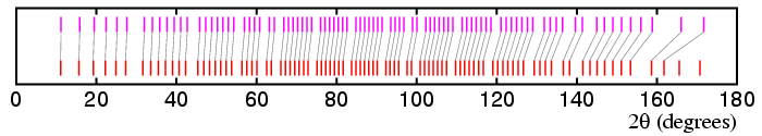
The strip diagram below shows how the
observed and
calculated
2θ positions vary for all of the reflections:
This illustrates the importance of indexing the low-angle reflections first even
though they provide the least accurate lattice parameters. If one assigns
hkl
triplets to high-angle data based on poor values of the lattice parameters, then
the probability of assigning incorrect values increases rapidly the higher the
2θ value:
in the above example, the observed peak at, say, 158.86° would
be matched to the 862 reflection of the 8 Å cell,
which is calculated to be at 158.65°, whereas the correct indices
are 772.
There is another reason why it is best to index the low-angle reflections first:
the density of reflections as a function of scattering angle is greatest
when 2θ ≈ 90°.
Again consider the cubic crystal system: since
Differentiation of n with respect to angle leads to the equation:
dn/dθ is a measure of the density of reflections,
i.e. the number of reflections in an interval δθ.
This equation shows that for a cubic material,
dn/dθ is greatest when
sin 2θ = 1, i.e. at
2θ = 90°.
This effect is illustrated in the reflection diagram shown above.
Conversely, the density of reflections is lowest at
2θ = 0° and 180°.
Hence low-angle reflections are easier to index!
For the cubic crystal system, the density of reflections is
symmetric about 2θ = 90°,
but for a lower symmetry crystal systems this is not the case and
the density of reflections is skewed to slightly higher angle:
the maximum density is for
2θ > 90°,
but the minimum is still at 0° (and 180°).
(As an aside,
this result has some bearing on the design of high-resolution angle-dispersive
powder neutron diffractometers
since it is clearly desirable to match the resolution function to
dn/dθ: hence they are designed so that the
best resolution is around 90° to 120° in
2θ.)
Indexing Cubic Materials
From the 2θ positions of the lines,
we can generate a table of sin2θ
values (as in the table below).
From equation [3] above, for a cubic system we can write
from which we can obtain the equation:
This equation shows that for a material with cubic symmetry, the ratio
of pairs of
sin2θ values must be equal to a
rational fraction.
Thus powder patterns of cubic materials may be indexed by simply examining
the ratios of pairs of sin2θ values
to see if the ratio is equivalent to the ratio of two
integer numbers. This can be done by trial and error, and is readily
done by hand. The ratios are easier to spot if the lowest-angle reflections are
used since these correspond to the smallest values of n.
Once values have been ascertained for n1
and n2, values of n for the
higher-angle reflections may be obtained since:
This approach avoids errors in the low-angle reflections propagating
through the calculation.
An accurate value of the lattice parameter a can then be
calculated by finding the correct value n for one of the
highest-angle / best-determined peaks.
The method is demonstrated in the table below for the yttria data shown in the
previous section:
the table lists values for the
ratios Rm:
where N is the peak number and
m is the initial value chosen for n1.
Since R must be integer, then it is clear that the value of
n for the first reflection cannot correspond to 1, 2, or 4. The
lowest value that it can have is 3, but note that higher multiples
such as n1 = 6 result in equally valid solutions.
Once n1 is known, then a can be determined and the
pattern can be indexed in full.
Referring to the complete table, the peak
at 164.3450° can be indexed with n = 93 from which
a value for a equal to 7.498 Å may be calculated. This
solution, however, is wrong! The reason is that the reflection at
46.9° has n = 15, and this value is impossible to
achieve from the sum of squares of three integer hkl values.
This demonstrates one pitfall with indexing: it is sometimes possible to
index a pattern with the wrong unit cell. The correct solution is
with n1 = 6, which gives
a = 10.604 Å.
In this very simple example, it is possible to take the analysis a step
further since the values of n that are obtained depend upon the
symmetry of the material. For primitive cubic symmetry
(e.g. Pm3m), there are only a
a few missing values of n. For body-centred cubic symmetry
(e.g. Im3m), all the odd values of n are missing.
Finally, for face-centred cubic symmetry
(e.g. Fm3m), the pattern is more complex: typical values
of n observed are 3, 4, 8, 11, 12, etc.
Although these methods may be useful for materials of cubic symmetry, they
are clearly less well adapted to the indexing of patterns from lower-symmetry
crystals. A more general approach will be discussed on the next page.
hkl
2θ
2θ′
2 δθ
![]()
8.00 Å
cell
![]()
7.92 Å
cell
100
11.059°
11.171°
0.112°
844
141.519°
144.986°
3.467°
sin2θ2 =
(λ / 2a)2 n2
sin2θ3 =
(λ / 2a)2 n3
etc.
n4 = n3
sin2θ4 /
sin2θ3
etc.
etc.
N
2θ
sin2 θ
R1
R2
R3
R4
R6
1 20.5017 0.03167
n1=1
n1=2
n1=3
n1=4
n1=6 2 29.1564 0.06335 2.00
4.00 6.00 8.00 12.00 3 33.7920 0.08447 2.67
5.33 8.00 10.67 16.00 4 35.9089 0.09502 3.00
6.00 9.00 12.00 18.00 5 37.9244 0.10559 3.33
6.67 10.00 13.34 20.00 6 39.8509 0.11614 3.67
7.33 11.00 14.67 22.00 7 41.7046 0.12671 4.00
8.00 12.00 16.00 24.01 8 43.4924 0.13727 4.33
8.67 13.00 17.34 26.01 9
46.9031
0.15838
5.00
10.00
15.00
20.00
30.01
(A complete table containing the complete set of
Y2O3 peaks is available.)
The
![]() generation program
can be used to demonstrate the above point.
generation program
can be used to demonstrate the above point.
![]() Course Material Index
Course Material Index
![]() Section Index
Section Index
![]() Previous Page
Previous Page
![]() Next Page
Next Page
| © Copyright 1997-2006. Birkbeck College, University of London. | Author(s): Jeremy Karl Cockcroft |