 |
Reflection Conditions
I. Centred Lattices |
 |
Reflection Conditions
I. Centred Lattices |
Centred Lattices
A typical layer of diffraction data from a single-crystal experiment is shown in the figure below for the zone plane hk0 (often called a zero-order layer):
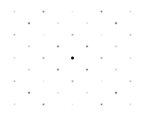
From these and other data, various unit cells can be deduced for the reciprocal lattice, enabling a choice of crystal system to be made.
The simplest unit cell for these data is shown below by the vectors in red. The corresponding lattice points are at the intersection of the lines shown in pale cyan:
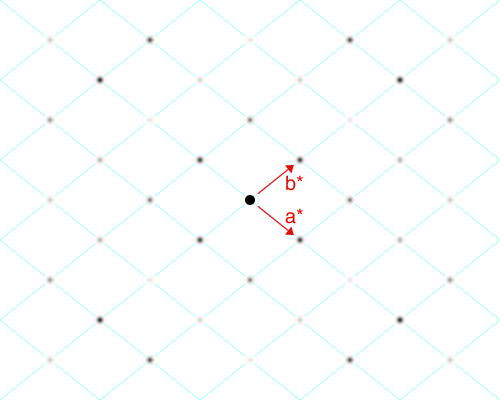
The third axis (c*) is chosen to be perpendicular to the screen for this data set. This choice of unit cell gives the largest reciprocal space volume V* and smallest real-space volume V. The reciprocal space unit cell has a* = b* and γ ≠ 90°, and its real space equivalent is shown in cyan in the diagram below:
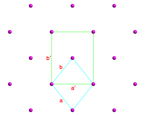
The cyan-coloured unit cell is primitive. However, in real space, it should be easy to see that a better choice of unit cell is likely to be the one shown in green in which the cell angle γ now becomes 90° (and a′ ≠ b′). The reason for this is that symmetry axes and planes are then likely to be parallel to the edges of the unit cell (see earlier section on symmetry). This corresponds to a C-centred lattice. The reciprocal space equivalent of the latter is illustrated in the next figure:
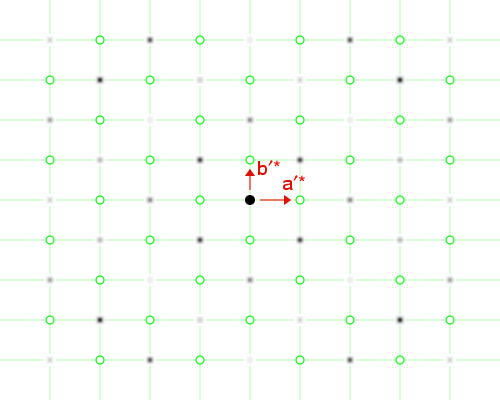
Since the C-centred real-space unit cell has twice the volume of the primitive one, its equivalent in reciprocal space (shown by the vectors in red) is now half that of the larger one shown earlier. Note the lattice points indicated by open green circles (o) now correspond to points in the diffraction data where there are no reflections, i.e. to systematically extinct reflections. For this hk0 plane, lattice points such as 100, 300, 010, 210, 120, etc., are systematically absent (i.e. extinct) in contrast to the lattice points 200, 400, 110, 130, 020, 220, etc., which are systematically present. This indicates that reflections may only be observed when the sum of the indices h + k is an even integer.
A little thought will show that
half of the reflections of the C-centred
real-space unit cell have to be missing since
the smaller reciprocal-space unit cell must give rise
to the same number of reflections as its primitive equivalent:
the number of reflections is independent of how the
crystallographer chooses the unit cell! In fact, for the above example,
all planes will have the reflection condition
In general, reflection conditions due to lattice centrings apply to all classes of reflections hkl; these are listed in the table below:
| Lattice Centring | Symmetry Operator(s) | Reflection Condition |
|---|---|---|
| P | - | None |
| A | x,1/2+y,1/2+z | hkl: k + l = 2n |
| B | 1/2+x,y,1/2+z | hkl: h + l = 2n |
| C | 1/2+x,1/2+y,z | hkl: h + k = 2n |
| F | x,1/2+y,1/2+z; 1/2+x,y,1/2+z; 1/2+x,1/2+y,z | hkl: k + l, h + l, h + k = 2n |
| I | 1/2+x,1/2+y,1/2+z | hkl: h + k + l = 2n |
| R | 1/3+x,2/3+y,2/3+z; 2/3+x,1/3+y,1/3+z | hkl: -h + k + l = 3n |
In the above table you should be able to see a correlation between the symmetry operator and the reflection condition that arises from it. It is the translational part of each symmetry operator that gives rise to the reflection condition, e.g. 1/2+x has an effect on the value of the index h. Other instances of this will be shown in the next few pages for screw axes and glide planes.
![]()
Note: The reflection condition for the rhombohedrally-centred
(R) lattice refers to the so-called obverse setting, i.e.
the coordinates of the centred lattice points are (0,0,0); (1/3,2/3,2/3);
and (2/3,1/3,1/3). (The alternative reverse setting with
centred lattice points (0,0,0); (2/3,1/3,2/3);
and (2/3,1/3,1/3) and reflection condition
hkl: h - k + l = 3n
is not normally used.)
| © Copyright 1995-2006. Birkbeck College, University of London. | Author(s): Jeremy Karl Cockcroft |