 |
Discussion: Description of the Structure |
|
|
Discussion: Description of the Structure |
Discussion: Description of the Structure
The description of the final refined structure needs to be presented as clearly possible, as it usually forms the main objective of the work. The structure is explained using a combination of a written and pictorial descriptions.
There is no set method for describing a structure. Generally, it is easiest to consider the structure carefully and to recognise the building blocks within it. These will generally comprise the molecular structure of the organic or organometallic molecule in a molecular structure, or a polyhedral unit, such as, an AlO6 octahedra or a SO4 tetrahedra, in an inorganic structure. The structures of these building blocks are first described noting such points as the conformation, the chirality or the amount of distortion that is evident in the building block. The way in which the building blocks pack to form the structure of the material is then described. The packing maybe through a direct linkage, for example, by sharing of the apices of polyhedra in inorganic materials, or through weaker intermolecular forces in an organic solid. It may then be appropriate to describe any remaining void spaces or channels in the resulting three-dimensional structure of the material and what they contain. Typical void filling entities include charge balancing metal cations and anions , and solvent molecules. Again, the spatial arrangement of these species and how they interact with the major building blocks in the structure need to be described.
As mentioned above the description of the structure is best achieved by giving a combination of text and graphical representations of different aspects of the structure. It extremely important to be able to produce illustrations of high quality, clarity, effectiveness and information content. Numerous graphics programs are available, many of them free, and your choice must depend on the range of features that each available program contains and how these meet your needs.
The following pictures are meant to give you some idea of the range of possible representations and styles.
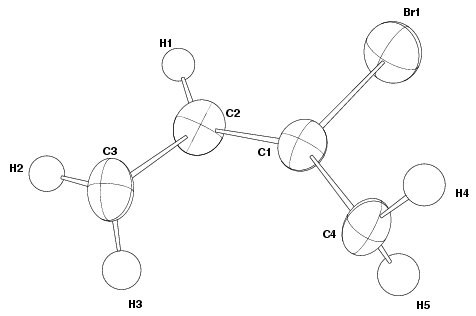
Asymmetric Unit
The first picture that many authors include in a structural paper is of the
asymmetric unit. This shows all the atoms in the asymmetric unit of the
structure, but as no symmetry equivalents are included, often does not show any
easily recognisable structural building blocks. However, it does allow the
reader to see all the atoms found in the material as well as their atomic
displacements if the atoms are represented as thermal ellipsoids. The thermal
ellipsoids represent the percentage probability of the electrons around the
atom being located within them as the atom vibrates. This probability level
must always be quoted in the Figure caption and is typically 50 %. Thermal
ellipsoids can only be produced when anisotropic temperature factors have been
refined, and are derived from the diagonal elements of the matrix representing
the aniostropic thermal motion of an atom. For atoms with only isotropic
refined temperature factors, thermal ellipsoids will be spherical if
represented. The thermal ellipsoid representation is exceptionally helpful in
pointing out atoms that are positionally disordered, or have large thermal
motion associated with them. The atoms of the asymmetric unit are labelled with
numbers corresponding to those used in the tables of atomic coordinates.


As shown in Figure 1, the atoms in the building unit can be represented by thermal ellipsoids that depict the atomic displacement of each atom, and this style can be applied to provide more information on the structure of the building block. There are various styles of thermal ellipsoid, some of which are illustrated below.
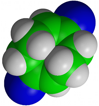
The above drawing styles give a poor idea of the external shape and steric requirements of a molecule. A more realistic representation is provided by a figure in which the atoms are shown as spheres having their van der Waals radii rather than much smaller arbitrary radii. These diagrams are refered to as "van der Waals" or "space-filling" plots and can be used to investigate the accessibility to certain atoms in a structure by other atoms, such as those involved in chemical reactions with the material.
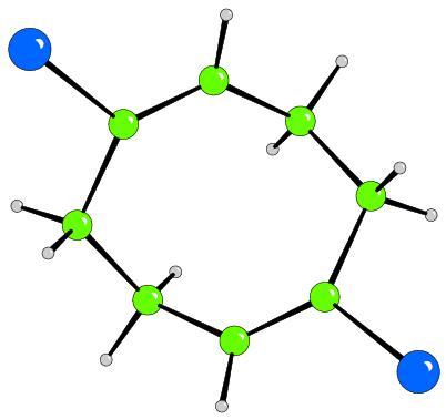
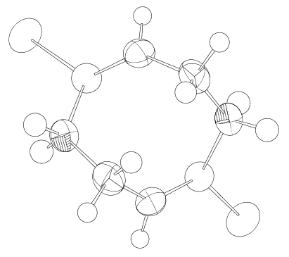
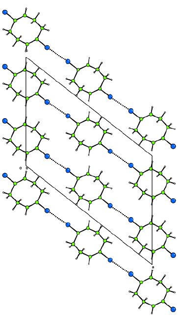
The 3-dimensional structure
A view of the full structure of the material is necessary to show how the
building blocks are linked to form the 3-dimensional structure and the
properties of this structure. Any of the plotting styles can be used for these
diagrams but be careful to choose a style and view that produce an
illustration that brings out the points you wish to make concerning the
structure and does not introduce unnecessary clutter. It is common to exclude
some atoms (for example, void filling ions or solvent molecules) in such a
figure to increase the clarity of the end product. It is often desirable to
show important interactions between molecules or groups in the structure by
using different bond styles, such as, dotted lines. The unit cell is normally
included in the representation of the 3-dimensional structure, with the axes
labelled.
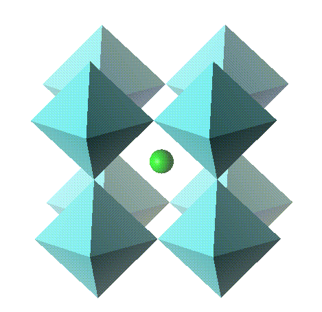
For inorganic compounds the building blocks tend to be formed from groups of atoms that form polyhedra. These polyhedra are linked together through their apices, edges or faces to build up the structure. For these compounds it is common to use a polyhedral represenation to visualise the 3-dimensional structure.
Interpretation
The main point of the description of the structure is that you can envisage the building blocks and crystal structure of the material. It is worth cross checking that the pictures and written description coincide with the structural aspects presented in the table of geometrical parameters. Most interpretation can be derived from thermal ellipsoid representations (Figure 1 and 4). The sizes of the ellipsoids give some indication of the disorder of atoms, their thermal vibration or even, when the ellipsoids are particularly large, that atoms have been incorrectly assigned in the structural model. For instance, in Figure 1, the ellipsoid for atom Br1 is greater than any of the other C atoms, indicating that the Br atoms are more disordered than the C atoms. It is assumed that the large ellipsoid of the Br atom arises from disorder and not from thermal vibration, because bromine is a heavier atom than carbon so it would be expected to have a smaller thermal vibration. The shape of the ellipsoids can be used to determine in which direction, along the three axes of the ellipsoid, the atom vibrates or is disordered the most. It is often useful to check that the relative size of the ellipsoids of different atom types correspond to the relative magnitude of the values presented in the table of anisotropic temperature factors. If no figures containing thermal ellipsoids are presented in the article then it is worth scrutinising the values of the anisotropic temperature factors to see if there are any unusual values hidden by the use of other representations, such as, ball and stick, of the crystal structure.
| © Copyright 1997-2006. Birkbeck College, University of London. | Author(s): Martin Attfield |