 |
The Inside Story
I. Residual Stress/Strain |
 |
The Inside Story
I. Residual Stress/Strain |
Residual Stress/Strain in Railway Tracks
The mechanical performance of engineering structures, such as chain links in
cranes, aircraft turbine blades, railway tracks, will depend on the interaction
between the applied stress (e.g. a load) and residual stresses created during
the structure's manufacture or in subsequent use. Such residual (internal)
stresses are linked to internal strain by means of simple equations involving
elastic moduli. Internal strain in polycrystalline objects manifests itself as
compression or extension of the individual crystallites in the object. So by
determining the small shifts in d spacings of local internal
crystallites, from their normal value, one can determine the local
stress/strain. If a material has a local crystallite which would normally have
a dhkl spacing value of, say d at a Bragg angle of
θ, then it can be shown (using differential calculus) that if this
crystallite is strained to a value ε, then d will change to
d (1+ε), and the Bragg angle will shift to a value

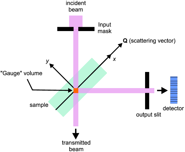
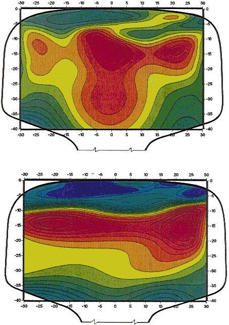
At any one traverse position, the measured shift in the Bragg angle determines the strain value in a direction perpendicular to the dhkl planes (Q in the diagram); further this value will be in effect the average strain over the 1 mm × 1 mm × 1 mm volume element. If circumstances suggest the strain is anisotropic then the object will need to be re-oriented several times and the shift re-measured for each orientation. Then the object is moved typically by 1 mm in one direction and the measurements repeated and so on. Finally a series is built up of stress/strain values, each value corresponding to a specific 1 mm × 1 mm × 1 mm volume element inside the object. So one eventually can build up a stress/strain map for the whole object. The figure below shows two very aesthetic stress contour maps for the head of a used railway track (for two stress/strain orientations - vertical and transverse respectively) obtained by Prof. Webster (Neutron News 2, 19 (1991)) using this method:

Everyone knows the general shape of the head of a railway track and this can be easily recognised in the outer-outlines in the figure. The residual stress levels are contoured using a colour coding ranging from low (blue and green) to high (200 MPa for red) residual stress. As expected the greatest variation occurs near the top surface where the track supports the wheels of the train, and this brings about some stress relief which is why the greatest residual stress is actually below the surface in the case of well-used rail tracks. Another feature is the asymmetry in the stress/strain patterns between the left-hand and right-hand: this is due to the true running line being offset by some 6 mm from the centre of the rail; i.e. the train wheels do not run on the exact middle of the track.
|
© Copyright 1997-2006.
Birkbeck College, University of London.
|
Author(s):
Paul Barnes Simon Jacques Martin Vickers |