 |
High-Resolution Diffractometers |
|
|
High-Resolution Diffractometers |
High-Resolution Diffractometers
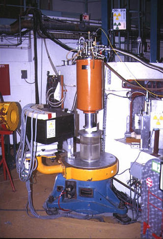
Powder neutron diffractometers are very large in comparison to laboratory X-ray instruments as shown by the scale in the figure below, which shows the layout of the high-resolution powder neutron diffractometer D2B at the ILL. The term high-resolution refers not to the smallest peak width in the powder diffraction pattern, but to the fact that the instrumental resolution function results in narrow peaks at high scattering angle. This is achieved by having large monochromator take-off angle as shown in the figure, which for this instrument is 135°. The layout of the instrument is "Debye-Scherrer" in the sense that it uses a cylindrical sample with transmission geometry.
With the detector bank placed so that the configuration of incident, monochromated, and diffracted beams is "Z" shaped, a focussing effect occurs: this produces a minimum in the resolution function for the diffractometer at high scattering angle as shown in the next figure. The resolution function is determined from the full-width of the peaks at half-maximum height (FWHM) as a function of scattering angle from a standard sample. (Note that if the detector bank was positioned on the other side of the diffractometer, which corresponds to the "negative" 2θ angles, the diffraction peak widths would simply increase as a function of increasing scattering angle.)
The large value of the monochromator angle is required so that
the wavelength dispersion, Δλ, of the
incident beam is kept small.
In order to achieve high resolution, the instrument must be able to count
neutrons with a very precise Bragg angle. This is achieved by the use of
Soller collimators placed in front of each
detector. Finally, given the relatively low flux available at neutron sources,
instrument efficiency is greatly improved by using many detectors at the
same time: the early powder neutrons diffractometers used only a single
detector; the first high-resolution powder instrument at the ILL known
as D1A had a bank of 10 detectors (though this has been increased
in recent years to 25);
while the highest-resolution powder diffractometer at the ILL, D2B, was
designed with 64 detectors so as to cover virtually the entire
2θ range.
The instruments function in a similar way to that of a laboratory diffractometer in that the detector bank of n detectors is step scanned in 2θ. In principle, a complete diffraction pattern can be obtained by just stepping through a 2θ range that is equal to the detector separation angle, which is 2.5° for D2B, and 6° for the older instrument D1A.
The use of Soller collimators on the high-resolution diffractometers enables cryostats and furnaces to be used without any problems from spurious scattering off the walls of these devices, e.g. Bragg scattering from the front and back aluminium walls of the cryostat tail is directly eliminated, the collimation having its maximum effect at 2θ equal to 90°, and no effect at 0° and 180°.
| © Copyright 1997-2006. Birkbeck College, University of London. | Author(s): Jeremy Karl Cockcroft |