 |
High-Flux Diffractometers |
|
|
High-Flux Diffractometers |
High-Flux Diffractometers
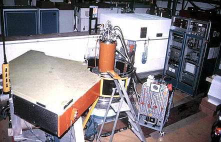
The previous page described the design of high-resolution neutron powder diffractometers at a reactor source. We now move on to the design of high-flux instruments where rapid count times are desired. As with X-ray case, the problem of step scanning diffractometers is that the diffraction may be changing as a function of time, e.g. during the heating up of a sample. In order to measure the diffraction pattern as a function of time it is necessary to use a diffractometer with a position sensitive detector (PSD) that covers a wide range of scattering angle. The figure below shows the setup for the medium- to high-flux diffractometer D1B at the ILL:
In order to obtain a high flux at the sample, the instrument uses a pyrolytic
graphite monochromator, which has a large mosaic spread,
Δθ/θ. The wavelength band pass,
Δλ/λ, is further increased by using a
low take-off angle (44.2°) for the diffractometer. The resulting wavelength
from the (002) crystal planes (for graphite
Instrument optimisation for high-flux implies that high-resolution has to be sacrificed: with such an instrument design the loss of resolution is not so much in the minimum of the peak width function, but with the angle where the minimum occurs. This is shown in the diagram below (which you should compare to the equivalent figure on the previous page):
In contrast to the high-resolution powder neutron diffractometers, scattering from cryostats and furnaces is more of a problem due to the nature of large angle PSDs; there is no collimation in front of the detector (though at least in principle radial oscillating Sollers could be used). Scattering from the sample environment has to curtailed by the use of carefully placed absorbing shields combined with large diameter aluminium tails for the cryostat and furnace.
Improvements
High-flux powder diffractometers benefit by being close to the neutron source, and the new instrument D20 is in the main reactor shell at the ILL. However, in order to make use of the higher flux available, a different design of PSD is required. The latest design replaces the conventional wires by microstrips deposited onto a glass surface. This also allows the "wire spacing" to be reduced from 0.2° to 0.1°, which provides more points in the profile of the powder diffraction peaks. The new instrument was also improved by the use of a variable take-off angle together with an increase in the detector size (covering 120° 2θ). This allows, at least in theory, neutron flux (and hence count times) to be balanced against d spacing resolution needs.
| © Copyright 1997-2006. Birkbeck College, University of London. | Author(s): Jeremy Karl Cockcroft |