 |
Monochromators |
|
|
Monochromators |
Monochromators
As with the X-rays produced at a synchrotron, so neutrons produced by a reactor have a spectrum of wavelengths. Most neutron diffractometers at reactor sources use angle-dispersive methods at constant wavelength to measure the powder diffraction pattern. As with X-rays, a single wavelength is selected from the white beam using a single-crystal monochromator.
Due to the size of neutron beams, very large single crystals are required for neutron monochromators, e.g. 105 mm3. Typical materials used are Cu, Be, C (as pyrolytic graphite), Ge, and Si. However, because the neutron beams are of relatively low intensity, perfect Ge and Si crystals have too small a band-pass (Δλ/λ) to be of much use as grown. In order to improve the incident intensity from Ge and Si single crystals, it is necessary to increase the mosaic spread. One method for doing this is to squash the crystals at high temperature and pressure to improve the mosaicity. However, in practice this often results in multicrystals (or broken crystals) and, consequently, poorly monochromated neutron beams (as in the original D2B at the ILL). A more recent development, developed in the USA, is to produce very fine slices of germanium crystal, and to glue them together in near perfect alignment, thus simulating on a rather large scale the effect of mosaic blocks.
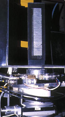
The photograph on the left shows the original germanium monochromator of the high-resolution powder diffractometer D2B at the ILL, which was constructed from 28 Ge crystals (of size 1cm × 1cm × 5cm). When the device is in situ, motors beneath the monochromator allow for both remote alignment and changes in wavelength.
In contrast to the X-ray scenario, the monochromator angle,
2θM, for neutron
diffractometers is not necessarily small:
for high-flux machines, the angle is typically
30° to 60°, while for high-resolution diffractometers, typical
values are in the range 90° to 135°.
Only discrete wavelengths are
available despite the white radiation from the reactor because
2θM is
normally fixed by the diffractometer position. In a few cases, the whole
instrument can be rotated about the monochromator axis using air-pads
thus providing more choice of incident wavelength (and resolution).
More commonly, discrete wavelengths are obtained by rotating the
monochromator crystal(s) as described below.

On the instruments D1A and D2B at the ILL, the germanium monochromator crystals were cut so that the normals to the -110 planes are along the vertical rotation axis, ω, of the monochromator. This enabled all planes of the type hhl to be available to monochromate the white neutron radiation, as shown in the above figure. Due to the crystal symmetry of germanium (which is cubic, space group Fd-3m), the allowed values of hhl are those with h and l being either both odd or both even. Typical planes used are 111, 113, 115, 335, etc., since reflections with odd h values do not diffract (due to crystal symmetry) the unwanted wavelength λ/2. To understand the relevance of this, remember that the direction of the normal of, say, the 111 reflection is identical to those of the 222, 333, etc., reflections. These higher-order reflections will also satisfy the Bragg condition simultaneouly to that of the 111 reflection, but for wavelengths λ/2, λ/3, and so on. However, due to space-group symmetry, 222 is a forbidden reflection, so that the corresponding λ/2 wavelength has zero intensity. (Reflection conditions and space-group symmetry will be discussed in much more detail later in this course.)
Monochromator crystals may be cut so that focussing of the beam occurs in the horizontal plane for the most commonly used crystal planes, as shown in the above figure. This geometric effect can provide a modest increase in flux at the sample position depending on the monochromator planes used. In the above example, based on D2B at the ILL, the crystals are cut with the front face parallel to (115), with the (335) planes providing the most frequently-used incident wavelength of 1.594 Å. In this instance, the wavelength is pure (i.e. λ/3 is absent) since the shortest neutron wavelength seen by the monochromator is approximately 0.65 Å.
To change the wavelength, the monochromator is simply rotated to another position. The actual angle of rotation depends solely on the interplanar angle between the current plane and the desired plane. It does not relate to the Bragg angle of the monochromator, which is fixed (as shown). However, the Bragg angle, 2θM, does determine the actual value of the wavelength selected by the monochromator.
In addition to horizontal focussing, vertical focussing is possible by applying a curvature to the whole monochromator. Typically many crystals are required in order to achieve this as shown in the top left-hand photograph. Once disadvantage of vertical focussing is increased axial beam leading to asymmetric peaks in the powder diffraction pattern at low scattering angles. However, the increase in beam intensity which results from reducing a pre-monochromator beam of, say, 30 cm down to one of, say, a few centimetres at the sample position, as shown in the above figure, is certainly worthwhile. You should be note that the curvature shown in the figure is schematic since the monochromator to sample to distance is relatively large (1 to 3 metres) and that the incident and diffracted beams do not lie in the same vertical plane.
Neutron Filters
Filters may be used at neutron sources in conjunction with monochromators. If the monochromator is designed to select a particular wavelength, λ, then it may also diffract shorter wavelengths such as λ/2, λ/3, etc., at the same monochromator angle. If the incident flux of neutrons is intense for the shorter wavelengths, then relatively large amounts of the unwanted wavelengths will be present with the fundamental wavelength, λ. The shorter "impurity" wavelengths can often be eliminated by the use of neutron filters.
Neutron filters are made of materials such as pyrolytic graphite
(or beryllium cooled in liquid nitrogen, N2, which has a
a very sharp "absorption" edge).
They actually work, not by absorption, but by diffracting the shorter
wavelengths sideways out of the main beam into a neutron absorbing material
such as B4C. The d spacing of
the filter is chosen such that the ratio
| © Copyright 1997-2006. Birkbeck College, University of London. | Author(s): Jeremy Karl Cockcroft |