 |
Instrument X-ray Optics
I. Reflection Geometry |
|
|
Instrument X-ray Optics
I. Reflection Geometry |
The earliest flat-plate diffractometers had poor intensities and peak widths due to lack of focussing. By contrast the modern flat-plate diffractometer has both good peak intensities and excellent resolution due to focussing of the diffracted beam. This reflection geometry, in which the divergent and diffracted beams are focussed at a fixed radius from the sample position, is commonly referred to as Bragg-Brentano geometry.
With the simplest form of this setup, the anode can be fixed and the sample and detector can be rotated by θ and 2θ, respectively. A common alternative is to fix the sample (usually in the horizontal position) and to move both the source and the detector by -θ and θ, respectively. The X-ray optics for this setup is illustrated schematically in the diagram below:
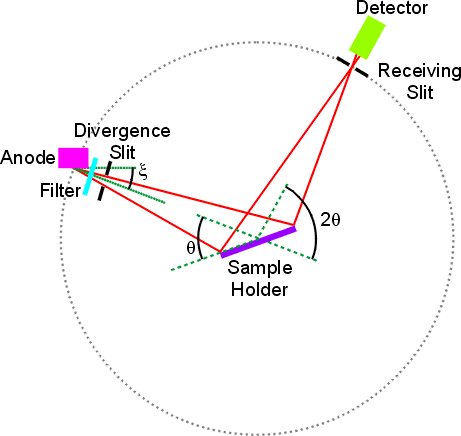
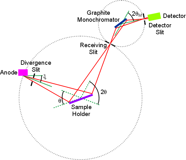
The dotted-circle centred on the sample position in these figures represents the goniometer circle on which the divergent source X-rays are "focussed" by diffraction from the flat-plate sample. Strictly speaking, true focussing only occurs when the sample plate has a curved (or hemispherical if rotated) surface. However, given that the footprint of the beam on the sample plate is considerably smaller than the radius of the focussing circle, then the flat-plate approximation works extremely well. As can be seen in the later figures, monochromators also have a monochromator circle associated with them, but in this case the monochromators can be curved (as in Johansson geometry) to ensure true focussing.
The tube is aligned so that the beam divergent on the sample is at angle ξ to the anode surface (which is typically about 6°), and the divergence of the beam is controlled by one or more slits after the source. In the absence of pre- or post-sample monochromator, an appropriate filter should be inserted after the X-ray source as shown. The illumination of the sample by the X-ray beam is proportional to cosθ and does not extend over the whole sample except at very low scattering angles. In order to get a good powder average, the sample is usually spun about an axis normal to the flat plate.
The divergence of the beam can be controlled by one or more slits positioned after the source. A typical X-ray slit is shown in the photograph below, the size of the slit being quoted in degrees in this instance, though sometimes they are given, for example, in millimetres.
 |
 |
Sideways divergence of either the incident or scattered beam can be controlled using Soller slits (shown in the right-hand photograph above) inserted in the X-ray beam path. These consist of a set of fine parallel foils which prevent angular divergence of the beam out of the θ/2θ plane. This gives a less asymmetric and narrower peak shape, especially at low scattering angles.
The next diagram shows the X-ray optics when a post-sample graphite monochromator is employed. The X-ray filter is no longer used. Again several slits may be used to control the divergence of the incident and diffracted beam. In addition, a beam catcher may be employed within the monochromator housing (not shown) to prevent non-monochromated X-rays from reaching the detector. With this setup, the source is normally fixed and the monochromator moved in unison with the detector arm. The Bragg angle for the monochromator, 2θM, is a preset constant determined by the interplanar distance, d, of the monochromator crystal.
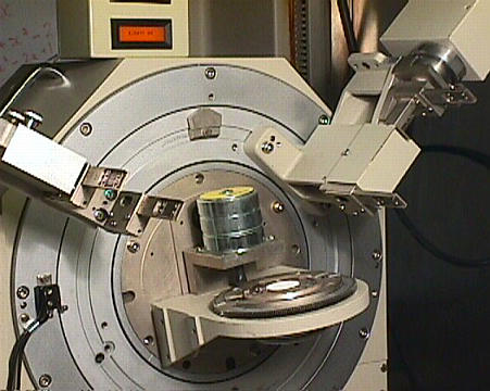
An alternative experimental setup is the pre-sample monochromator shown in the final diagram below and illustrated by the two photographs at the bottom of the page. In this setup, both the X-ray source and the monochromator are fixed, and only the sample and detector rotate about the θ/2θ axis of the goniometer. In order to achieve separation of the Kα1 and Kα2 wavelengths together with a reasonable X-ray intensity, the pre-sample monochromator is curved so that the X-rays are focussed (or nearly focussed depending on the exact curvature used) from all parts of the crystal.

The left hand photograph shows the position of the X-ray tube housing, primary-beam monochromator, and θ/2θ goniometer with a white powder mounted in flat-plate holder. The motor for spinning the sample is clearly visible just above the sample position. The right-hand picture shows the position of both incident and diffracted beam slits plus the scintillation detector mounted on the 2θ circle of the goniometer. Post-sample Soller slits are mounted in the housing between the post-sample anti-scatter slit and the receiving slit of the detector.
 |
 |
| © Copyright 1997-2006. Birkbeck College, University of London. | Author(s): Jeremy Karl Cockcroft |