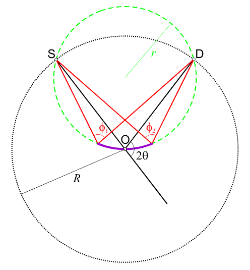
![]() In the following diagram, the source is represented by the point S, the
receiving slit on the detector by the point D, and
the centre of the goniometer circle(s) by the point O.
All three points lie on a circle known as the focussing circle, as shown
in green. The black dotted line represents the goniometer circle around
which the detector (and source if θ/θ geometry) moves.
The goniometer circle has a fixed radius, R, but the radius of the
dashed-green circle, r varies from ∞ to R/2 as the 2θ
angle varies from 0° to 180°.
In the following diagram, the source is represented by the point S, the
receiving slit on the detector by the point D, and
the centre of the goniometer circle(s) by the point O.
All three points lie on a circle known as the focussing circle, as shown
in green. The black dotted line represents the goniometer circle around
which the detector (and source if θ/θ geometry) moves.
The goniometer circle has a fixed radius, R, but the radius of the
dashed-green circle, r varies from ∞ to R/2 as the 2θ
angle varies from 0° to 180°.

Due to the geometric property of circles, X-rays produced from
S and diffracted from any point
on the green circle by angle 2θ (e.g. from the "sample" shown in purple)
all arrive at exactly the same point D, i.e.
the relationship
In the figure, the "sample" is shown curved, and for perfect focussing this curvature would have to vary according to the scattering angle 2θ, an impossible situation for powder samples in a flat-plate holder! In practice, a perfectly flat sample surface is used: conseqently the diffracted beam is not quite so perfectly focussed, and this provides one contribution to the linewidth of the peaks in the diffraction pattern. The diagram above is highly exagerated in the sense that the footprint of the incident beam on the sample is excessive. Furthermore, the footprint decreases considerably as the sample angle θ is increased. Thus r decreasing as 2θ increases has a less dramatic effect on the linewidths than one might initially expect.
| © Copyright 2002-2006. Birkbeck College, University of London. | Author(s): Jeremy Karl Cockcroft |