 |
X-ray Detectors |
|
|
X-ray Detectors |
X-ray Detectors
The two most common types of X-ray detector used in the laboratory for powder diffraction (excluding the case of X-ray film) are the scintillation and the gas-filled detectors, both of which are described below.
Scintillation Detectors
In the scintillation counter, the conversion of X-ray photons into an electrical signal is a two-stage process. The X-ray photon collides with a phosphor screen, or scintillator, which forms the coating of a thallium-doped sodium iodide crystal. The latter produces photons in the blue region of the visible spectrum. These are subsequently converted to voltage pulses by means of a photomultiplier tube attached directly behind the scintillator. The number of electrons ejected by the photocathode is proportional to the number of visible photons which strike it, which in turn is proportional to the energy of the original X-ray photon. Due to a large number of losses, the energy resolution of the detector is poor, and as such it cannot be used to resolve X-ray photons due to Kα and Kβ radiation. However, it has a very high quantum efficiency and a very low dead time making it the ideal detector for the point intensity measurements required for step-scanning diffractometers.
Gas-filled Detectors
The second type of detector commonly used in the laboratory is the gas-filled detector. This detector works on the principle that X-ray photons can ionize inert gas atoms such as argon or xenon into an electron (e-) and ion (e.g. Ar+) pair. The ionization energy required to eject an outer electron is low (10-20 eV) compared to the energy of the X-ray photon (8 keV) so that one X-ray photon can produce several hundred ion pairs. A wire placed inside the detector is set to a potential of about 1,000 V. This accelerates the electrons of the ion pair towards the wire causing further ionization and an enhanced signal by gas amplification. The burst of electrons on the wire is converted into a voltage pulse which is then shaped and counted by the electronics. In order to minimise the dead time of the system, a quenching gas such as methane (CH4) is mixed with the inert gas (e.g. 90% Ar : 10% CH4).
A disadvantage of gas-filled detectors is their loss of linearity at high count rates, but they have a better energy resolution than scintillation detectors. The simple gas-filled detector is much less-commonly used than a more sophisticated form known as a position sensitive detector or PSD.
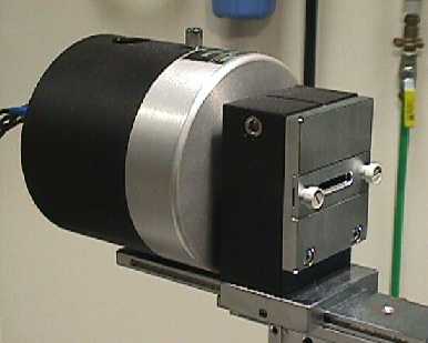
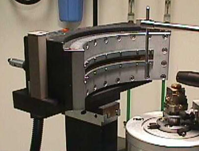
PSDs are gas-filled detectors with a long poorly-conducting anode wire to which a high tension voltage is applied at both ends. In consequence, the pulse moves towards both ends of the wire simultaneously and by measuring the rate at which it arrives at both ends of the wire, it is possible to determine from whereabouts on the wire the pulse originated. The pulses are stored in a multi-channel analyser (MCA) device according to the pulse position on the wire. This enables PSDs to record data over a whole range of scattering angles, which can be useful where speed of acquisition is crucial, e.g. in time-resolved powder diffraction or thermodiffractometry. PSDs come in a variety of shapes and sizes: Small PSDs usually have a straight wire and can only collect data over, say, 5-10° 2θ. Large PSDs require curved wires, but collect over a much wider range of scattering angle. In addition, some gas-filled PSDs are sealed, while others require a continuous flow of gas for their operation. Linear and curved PSDs are illustrated in the photographs below:
 |
 |
Calibration
In contrast to the scintillation and simple gas-filled detectors used for point intensity measurements, position sensitive detectors require careful calibration for both wire position and efficiency so that both scattering angles and intensities can be reliably determined. For each channel of the MCA an exact 2θ position is required together with an efficiency coefficient. The wire efficiency can be determined using a sample such as an amorphous iron foil that produces a very high flat background and no Bragg peaks. The 2θ calibration is achieved by scanning the different parts of the detector through the Bragg reflection of a strong peak (or peaks), e.g. the Si 111 peak. For very large curved detectors, the 2θ calibration has to be made using many diffraction peaks.
| © Copyright 1997-2006. Birkbeck College, University of London. | Author(s): Jeremy Karl Cockcroft |