 |
Asymmetric Unit |
 |
Asymmetric Unit |
Asymmetric Unit
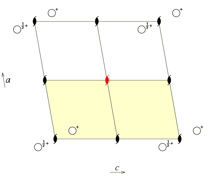
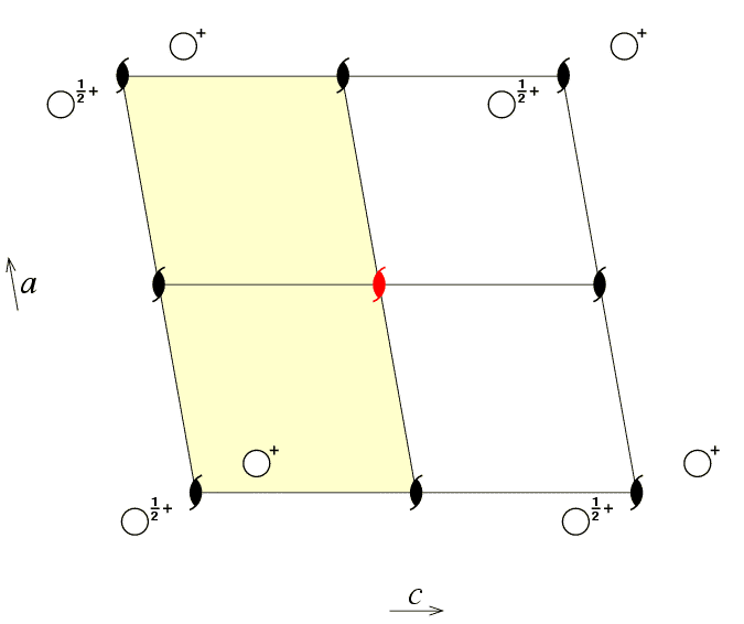
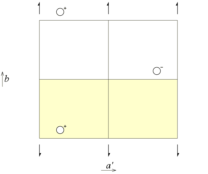
The asymmetric unit of a space group is that part of the crystallographic unit cell which can be used to generate the complete unit cell by the symmetry of the space group. Only the coordinates of the atoms in the asymmetric unit are deposited in the various crystallographic databases. The generation of the remainder of the contents of the unit cell is normally a black box operation done by a computer program. The choice of asymmetric unit is not unique as illustrated by the following three diagrams for the monoclinic space group P21.
The first figure shows an asymmetric unit (shaded in pale yellow)
defined by the coordinate ranges

The next figure shows an alternative choice of asymmetric unit for
the same space group, but this time with the asymmetric unit defined
by the coordinate ranges

Can one choose an asymmetric unit with a different range for y? The third figure of space group P21 viewed down the c axis shows just such a possibility for the asymmetric unit.

These figures illustrate that the choice of the asymmetric unit is something fixed by the crystallographer and that it is choice is not an intrinsic property of the crystal. Fourier programs that calculate electron density maps make use of asymmetric units with straight edges as shown in the three previous illustrations. However, the asymmetric unit is not required to have nice straight lines as shown in the figures! In fact, crystallographers frequently choose asymmetric units that are determined by the "outline of the molecule", which is all but linear. This is shown schematically in the figure below for the organic molecule S(-)-α-bromobenzylmethylsulfone [1], illustrated using coordinates extracted from the Cambridge Structural Database:

It is usually more convenient to describe a crystal structure in terms of atomic coordinates of atoms that belong to a single complete molecule; by doing this the crystallographer is implicitly considering an asymmetric unit of the type outline in purple above and which extends just beyond the limits of the unit cell. Note that although both methyl (-CH3) groups are shown outside the unit cell, there will also be two methyl groups (not shown) within the unit cell; the latter belong to two other molecules whose centres of gravity lie outside the unit cell.
You should note that, whatever choice is made for it, the asymmetric unit will always comprise one half of the volume of the unit cell for this particular space group. The number of asymmetric units per unit cell for each space group is determined by the lattice centring (i.e. P, A, B, C, F, I, or R) and the crystal class. The concept of crystal class will be discussed next.
[1] Crystal structure by G.D.Andreetti, G.Bocelli, & P.Sgarabotto published in Crystal Structure Communications, (1973), 2, 519.
| © Copyright 1995-2006. Birkbeck College, University of London. | Author(s): Jeremy Karl Cockcroft |