 |
Symmetry Diagrams
II. Stereographic Projection |
 |
Symmetry Diagrams
II. Stereographic Projection |
Stereographic Projection
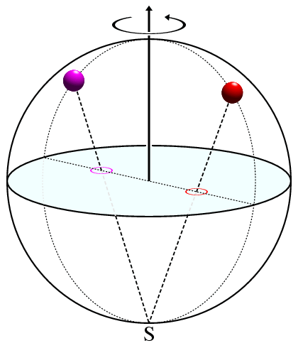
The second type of symmetry diagram used by crystallographers is the stereographic projection. This projection, which is used to show symmetry about a fixed point, is illustrated in the figure below:

The diagram represents a sphere which will be described as though it were a globe. Thus the point S indicates the south pole of the globe. The light blue plane passing through the centre of the globe represents the equatorial plane. The red and magenta objects on the surface of the sphere, which could represent atoms or molecules, are projected onto this plane as follows: An imaginary line is drawn between an object in the northern hemisphere (e.g. the red or magenta balls) and the south pole (S) while for objects in the southern hemisphere, the line is between the object and the north pole (see similar illustration).
In the projection diagram, the position of the object is shown at the point where the dashed line intersects the equatorial plane. These points for the red and magenta balls are shown as red and magenta circles in the above figure. Note that although the figure has been drawn so that the red and magenta balls are related by a twofold rotation axis (shown by the vertical axis and rotation arrow), the symmetry is not immediately recognisable since the red and magenta balls may appear to be at different heights in this "3-dimensional" figure.
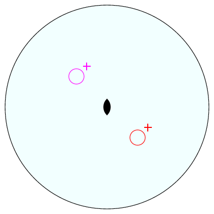
The equivalent stereographic projection is shown below with the positions of the red and magenta balls marked by the coloured circles:

The lens-shaped symbol at the centre of the figure indicates the twofold rotation axis perpendicular to the plane of projection: That the two objects are related by a twofold rotation axis should now be self evident. The plus ("+") signs indicate that the object has been projected from above the plane of projection, i.e. from the northern hemisphere. Minus ("-") signs indicate the contrary situation, i.e. an object below the plane of projection in the southern hemisphere.
The twofold rotation axis does not involve any change of handedness
in constrast to the point of inversion described in an earlier section.
Crystallographers indicate a change of handedness in symmetry diagrams
by placing a comma (",") inside the open circles:
Sometimes, objects in the northern and southern hemispheres will project
onto exactly the same point in the equatorial plane.
This situation occurs when the equatorial plane has mirror symmetry.
The superposition of the objects is shown using the following symbol:
The right-hand part with the plus sign indicates an object above the equatorial plane and the left-hand part with the minus sign shows an object below the plane and with the opposite handedness.
You may be wondering by now why stereographic projections are used by crystallographers when the flat projection is available. The reason is that stereographic projections are best for showing the symmetry about a point in space: This point in space could be the centre of an organic/organometallic molecule or the centre of the reciprocal lattice containing the diffraction data.
| © Copyright 1995-2006. Birkbeck College, University of London. | Author(s): Jeremy Karl Cockcroft |