 |
Insertion Devices |
 Course Material Index
 Section Index
 Previous Page
 Next Page
Insertion Devices
Although a detailed account of synchrotron radiation devices is outside the
remit of this course, a brief description of other magnet configurations is
necessary.
When we considered the layout of a storage ring,
we saw as many straight sections as dipole magnet sections.
If we were to have a magnet
system that accepted and returned electrons in the same direction then they
could be inserted into these straight sections without affecting the
operation of the dipole magnets, thereby doubling the number of potential X-ray
magnet sources. Such systems are referred to as insertion devices of
which wigglers and undulators are two basic kinds.
A. Wigglers
The radiation emitted by a dipole magnet (illustrated on the previous page) is
characterised by the parameter λc, the
critical wavelength by which the total power spectrum reaches 50%. A standard
formula relates λc to the electron beam
energy E (in GeV) and the bending magnetic field B (in Tesla):
Therefore if for a given energy E we can increase B, and hence
the radial acceleration, we would shift
λc to a shorter wavelength thus the
X-rays would on average have shorter, more penetrating, wavelengths. Such a
device is therefore often referred to as a wavelength shifter. A
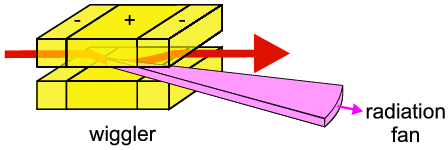
so-called wiggler is both an insertion device and a wavelength shifter. A basic
version is depicted below:
 In its simplest form, the wiggler contains three magnets; the outer two magnets
are opposed (magnetic field in opposite direction) to the central magnet.
Basically the first (outer) magnet bends the electron path in the "wrong
direction" (i.e. opposite curvature from the overall synchrotron ring), the
second (middle) magnet over-compensates for this, and the third (outer) magnet
brings the electron path back to its original direction (the overall motion
could be described as a wiggle, hence the name). The over-compensation
in the middle section is brought about by a very intense magnet (usually a
super-conducting magnet with typically a 5-6 Tesla magnetic field
strength) and the resulting tighter local curvature means that a greater radial
acceleration is brought about with the consequent production of harder X-rays
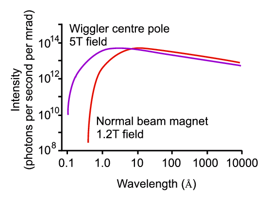
(i.e. higher energy photons). This is illustrated below where we can see that
the wiggler spectrum resembles the dipole spectrum but shifted (by several
tenths of an Ångstrom) towards shorter wavelengths. As the scale is
logarithmic, this is more significant than is immediately apparent from the
diagram.
 For long wavelengths there is little difference in
the two performances, but if the region of interest is in the extreme left side
of the spectrum (typically around 0.4 Å) the intensity from the
wiggler could be orders of magnitude more than from the dipole magnet. Clearly
wiggler magnets are very important for short wavelength powder diffraction
experiments.
B. Undulators
 It consists of many (typically 20-30) alternating low field magnetic poles.
This therefore produces an alternating series of inward and outward electron
accelerations (such motion being described as undulations) each with its
individual radiation emission from each pole. At some point downstream from the
undulator these radiation emissions will overlap and interfere with each other,
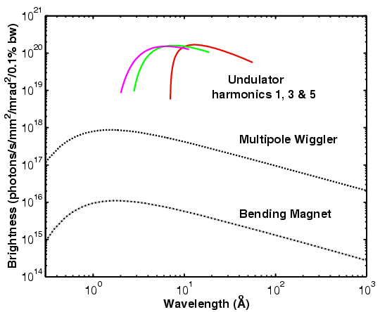
sometimes constructively and sometimes destructively. Depending on the exact
configuration of the undulator, the resulting power spectrum as shown below can
look very "lumpy" by comparison to the smooth dipole or wiggler spectra.
 By choosing the magnet parameters and interference point carefully, the
undulator spectrum can be designed so that one of the larger positive bumps
corresponds with a wavelength region of interest. This is not the same action
as a monochromator (see later) but what one is effectively doing is improving
intensity of part of the spectrum at the expense of other parts. Undulator
magnets have turned out to be popular insertion devices for the large third
generation super-sychrotrons where their space requirement (excessive length
due to the many poles) is less of a problem.
 Course Material Index
 Section Index
 Previous Page
 Next Page


