 |
Beam Conditioners |
 |
Beam Conditioners |
Beam Conditioners
So far we have described the operation of the synchrotron storage ring and the radiation produced therein. However this radiation still needs to be transported to the user. In practice this done by feeding off the radiation from the magnets down beam-pipes maintained, usually, at the same ultra-high vacuum as the storage ring. These beam pipes lead from the storage ring to the user's instrument contained within a purpose-built hutch (which is sometimes referred to as a station). Except in special cases, the radiation needs to emerge from the synchrotron's vacuum and enter the environment of the user's instrument. This is achieved using a window between the two; in the case of X-rays a thin (e.g. 100-200 μm) beryllium sheet is invariably used: this is effectively X-ray transparent for wavelengths shorter than say 2.5 Å.
Beam conditioners are devices which alter the properties of the radiation beam en route to the instrument.
Mirrors
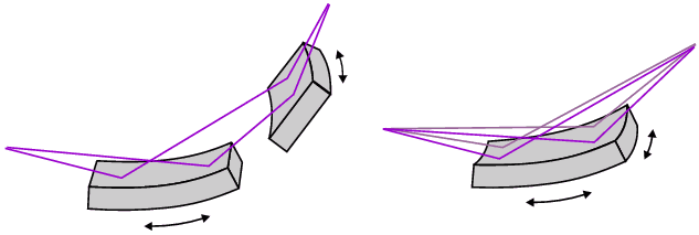
Mirrors are one type of beam conditioner. Located between the magnet and the window, they are used to alter the convergence or divergence ("focus") of the X-ray beam. They do this by exploiting the effect of grazing reflection of X-rays from a curved surface. For example a divergent (albeit slightly) synchrotron beam can be converted into a parallel beam (see below, left side) or convergent beam (see below, right side) by the use of a deliberately bent mirror surface:

Monochromators
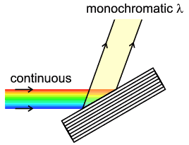
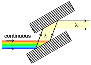
Another beam property that requires consideration is wavelength which usually needs to be selected from the continuous synchrotron spectrum. This is done using a monochromator, normally located after the X-ray window outside the vacuumed storage ring in the station environment. Monochromators work by orienting a crystal, placed in the path of the beam, so that it preferentially diffracts only the X-ray wavelength satisfying Bragg's Law. Monochromators are discussed in more detail elsewhere in the course so at this point we only need note a few obvious points. The arrangement used can be selected from the three illustrated below: progressively, the first arrangement (single bounce) unavoidably alters the direction of the beam; the second (double bounce) maintains direction but not height; the third (4-bounce) maintains direction and height.

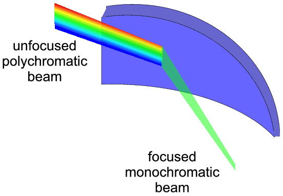
Finally we should note the device, often referred to as the triangular bent crystal, which focuses the beam while acting as a monochromator. (see below).
In practice optimising the beam condition from the above somewhat bewildering choice of possibilities depends on many factors: these include the state of the initial synchrotron beam, the specification of the powder diffractometer, the requirements of the experiment and the actual physical space available.
|
© Copyright 1997-2006.
Birkbeck College, University of London.
|
Author(s):
Paul Barnes Simon Jacques Martin Vickers |