 |
Mode (2): Multiple Foil (Hart-Parrish) |
 Course Material Index
 Section Index
 Previous Page
 Next Page
Mode (2): Multiple Foil (Hart-Parrish)
This mode is often referred to as the Hart-Parrish mode after two of the
authors in a relevant publication (Parrish, Hart & Huang, Journal of Applied
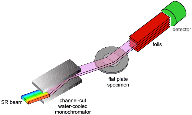
Crystallography, 19, 92-100 [1986]). This method uses a series of thin
finely spaced metal foils in front of the detector (note their orientation is
quite different from the "Soller" slits you might have come across with
laboratory powder diffractometers) as illustrated below.
 Typical foils are made of stainless steel. On station 2.3 at the Daresbury SRS
they are 350 mm long, 0.05 mm thick and separated by 0.1 or
0.2 mm.
This means that only a narrowly divergent beam (0.03° or 0.06°,
respectively) will pass
through the foils and reach the detector, since X-rays more divergent than this
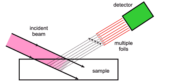
will hit the foils and be absorbed. Now if we imagine the intersection of the
plane of these foils with the incident (parallel) beam, then a region is
defined (see schematic below) from which all detectable diffraction must
originate. This feature of defining the diffraction region can be exploited in
several ways (also see schematic below):
-
we can choose which part of the specimen (e.g. the surface layer, or layers
beneath the surface) we wish to study;
-
in the case when the sample is in the form of a thin layer, we can ensure that
the diffraction detected only comes from the sample and not the supporting
medium;
-
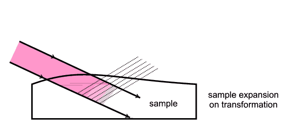
A good diffraction pattern is obtained even while a specimen moves, expands or
shrinks during a phase transformation - in the normal mode, parts of the sample
would move "off centre" and cause peak broadening in the pattern. But with the
multiple foil arrangement each foil corresponds to an "on-centre" defined
region of diffraction.

 The main disadvantages of this mode are that the diffraction peak shape can be
less regular and that the overall resolution is limited to only "medium-high"
resolution. However for the correct application the results can be strikingly
good. An example will be shown in a later part of the course.
 Course Material Index
 Section Index
 Previous Page
 Next Page


