 |
The Reciprocal Lattice |
 |
The Reciprocal Lattice |
The Reciprocal Lattice
You will have noticed that the term "Reciprocal Lattice" has crept several times into the discussion. This falls naturally out of the Diffraction Theory as representations of the rules for when diffraction occurs in the cases of a one-, two- and three-dimensional crystals. In fact the concept of the reciprocal lattice is used by many crystallographers as a way of visualising the many diffraction possibilities available by re-orienting or rotating a single crystal. Although diffraction can still be understood without the concept of the reciprocal lattice, it is widely used and so some summarising remarks are in order. A full explanation would be outside the remit of this course.
Single Crystal: Two geometrical devices, the Ewald Sphere and the Reciprocal Lattice are combined. The devices are totally abstract: they are used simply because they are convenient visualisation tools. The first, the Ewald Sphere, is normally represented as a sphere of radius 1/λ, where λ is the wavelength of the X-rays (or other radiation) being used. It is illustrated below in two dimensions only.
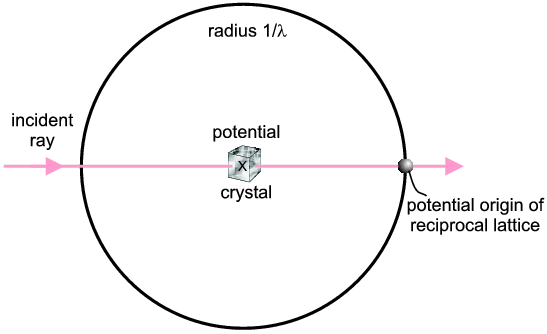
The incident direction of the X-ray is indicated. Potential diffracted X-rays can be along any radius from the centre of the sphere to the circumference (in fact they could be out of the plane of the diagram as it is really a sphere). So basically the Ewald Sphere represents the experimental possibilities λ, possible 2θs etc.).
The next component is the Reciprocal Lattice which represents the scattering possibilities of a given crystal (planes, then lines, then points for 1D-, 2D- and 3D-crystals respectively). There are rules about the precise dimensions of the reciprocal lattice for the different types of crystal systems but we do not need to get involved in them here; however, you will have noted that reciprocal parameters keep occurring (we have seen planes 1/a, 1/b and 1/c apart, and finally the parameter 1/d) hence "reciprocal lattice" is a good name in both senses (in the just-mentioned algebraic sense, and that it is an alternative "view" of crystal structure). Suffice to say that many crystallographers think of the reciprocal lattice almost as though it were real; which, of course, it is not; its just an abstract property of the crystal whereas it is the crystal which possesses the "real lattice". The reciprocal lattice basically consists of points on a regular grid which represent diffraction possibilities. Each point can be labelled with a Miller index (h,k,l) which corresponds to the planes from which diffraction would occur (if it did). A schematic reciprocal lattice is illustrated below but showing just a two-dimensional slice (for simplicity). In fact the illustration shows just one layer (l = 0) corresponding to all possible h,k,0 reciprocal lattice points within view. The next layers, above and below this zero layer, would be h,k,1 and h,k,-1; the next layers after that h,k,2 and h,k,-2, and so on, so that all h,k,l can eventually be covered over three dimensions (note: negative numbers, -n, are often written with a bar above the number and pronounced "bar n").
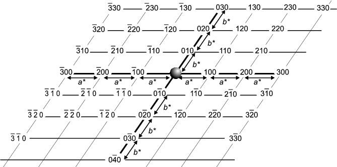
You will notice that the reciprocal lattice points are on a regular grid termed
the reciprocal lattice. The units of this lattice are a*, b* and
c* - this is reminiscent of the original (real) crystal which you will
remember is divided into unit cells of sides a, b and c.
From the origin one can get to any reciprocal lattice point,
h,k,l by moving h steps of a*, then k
steps of b* and l steps of c*.
This is summarised by the vector
equation:
The final trick is to add the Ewald Sphere diagram to the Reciprocal Lattice
diagram. This symbolises setting the experimental conditions (Ewald Sphere) for
a given crystal (Reciprocal Lattice). Diffraction occurs whenever a reciprocal
lattice point touches the Ewald Sphere. For an arbitrary crystal orientation it
may turn out that there is no such coincidence but then the crystal can be
rotated, and the reciprocal lattice will rotate with it, until a reciprocal
lattice point comes into contact with the Ewald Sphere and then diffraction
occurs. The next figure illustrates this for the case where
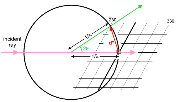
So this figure illustrates the case of a crystal (and its reciprocal lattice) oriented to cause diffraction from the h,k,l = -2,3,0 planes. The direction of the diffracted ray is indicated in green. The vector joining the Origin to the operative reciprocal lattice point is denoted d* and is called the reciprocal lattice spacing (shown in red). In fact it is equal to exactly 1/d (hence another reason for the name reciprocal lattice) and its direction is perpendicular to the h,k,l planes; again crystallographers think of d* as synonymous with the diffracting planes and similar notations are used (e.g. dhkl = real planar spacing; d*hkl = reciprocal lattice spacing).
Powder: As already stated the Ewald Sphere + Reciprocal Lattice concepts are well-exploited by single crystal crystallographers. One might ask "what is the reciprocal lattice of a powder?" Well if each crystallite has a reciprocal lattice, as in the previous figure, then a single component powder will consisting of millions/billions of identical reciprocal lattices but randomly oriented with respect to each other. In the statistical limit the individual crystallite reciprocal lattice points will join up to form continuous circles (actually spheres in three dimensions). For example the -2,3,0 reciprocal lattice point illustrated above will occur in every orientation possible (not just the one orientation shown) meaning that the reciprocal lattice point will broaden into the surface of a sphere with radius d* and centred on the Origin. So the Ewald Sphere + Powder Reciprocal Lattice consists of the Ewald Sphere being intersected by many spheres, each of radius d*hkl for a given h,k,l: two spheres intersect as a circle so for each h,k,l the diffracted rays will describe a cone. This real space view of powder diffraction is often used during this course. The use of the Ewald Sphere + Reciprocal Lattice concepts are generally speaking not so useful in the field of powder diffraction, but they have been briefly mentioned here for completeness.
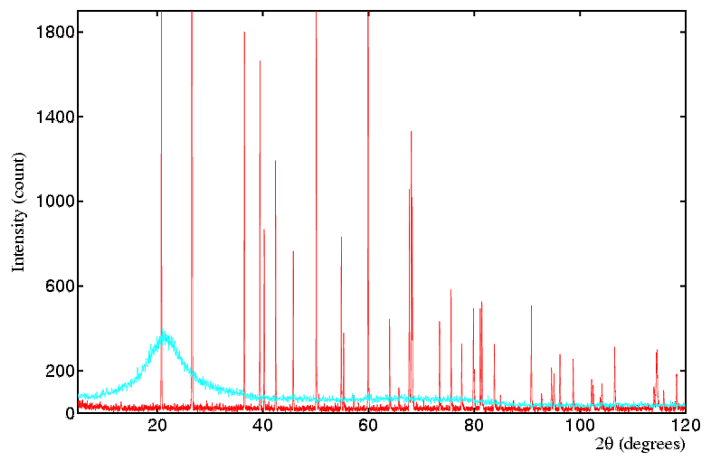
Amorphous Materials: Amorphous materials (glasses, liquids etc.) have no regular crystalline structure, therefore the concept of a reciprocal lattice does not apply, as such. It is often said that amorphous materials have no structure. This is not strictly true: they are directionally isotropic, meaning there are no unique axes as with a crystal, so that any one direction is statistically the same as any other direction in the material. But there is some weak statistical structure in the sense that atom/molecule positions are not random, but in practice the condensed packing requires that neighbouring atoms/molecules occupy positions that are neither too close nor too far from each other. There is not the strongly constructive interference that occurs in a crystal when billions of atoms scatter in phase (at the Bragg angle) but there is a high statistical likelihood of pairs of atoms/molecules in an amorphous material being at certain separations (close to the sum of their radii) that causes some positive scattering intensity. The end result is that if a liquid or glass replaces a powder in a powder diffraction experiment, one collects a scattering pattern that has one, two or more weak broad bands of intensity. The information content in these bands is extremely low compared to a conventional single crystal or powder pattern. However such limited information has its uses, though that is well outside the remit of this course. The main message from this discussion is to recognise that your powder sample might contain amorphous material (particularly if you are in the region of a amorphous to crystalline material transition) and in such cases you will observe, in addition to the sharp diffraction peaks, a more slowly varying underlying amorphous material scattering pattern that is distinct from a normal background. The diagram below compares patterns from a crystalline powder of SiO2, quartz, (red) and its amorphous equivalent, quartz glass (cyan).
Alternative Definition: It has to be pointed out that some crystallographers use a later, alternative, scheme to the above in which the Ewald sphere has a radius changed to unity (rather than 1/λ) and the reciprocal lattice vector has its length changed to λ/d (rather than 1/d). The original diagrams have thus been effectively multiplied by λ for the dubious advantage of making the lengths free of reciprocal units. Given that the purpose of the Ewald sphere & reciprocal lattice concepts are to aid visualisation (rather than to draw actual figures to some unit-less scale) it totally escapes the understanding of this author why such crystallographers persist in perpetuating this confusion. Having done the duty of mentioning this alternative, all future uses on this course will now refer to the sensible definitions explained above.
|
© Copyright 1997-2006.
Birkbeck College, University of London.
|
Author(s):
Paul Barnes Simon Jacques Martin Vickers |