 |
X-ray Filters |
 |
X-ray Filters |
X-ray Filters
Function
The previous pages showed that the spectrum from a sealed X-ray tube is composed of several X-ray lines. Laboratory powder diffraction requires an X-ray source that is essentially monochromatic and so the Kβ line in the X-ray spectrum needs to be removed. Metal foil filters are one way of achieving this.
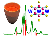
The photograph shows the typical metals used to filter X-rays produced by a sealed X-ray tube, i.e. Ni, Fe, Mn, V, or Zr. Filters preferentially reduce the intensity of the Kβ line in the X-ray spectrum compared to Kα as explained below. Note that absorption filters cannot be used to remove the unwanted Kα2 component from Kα radiation.
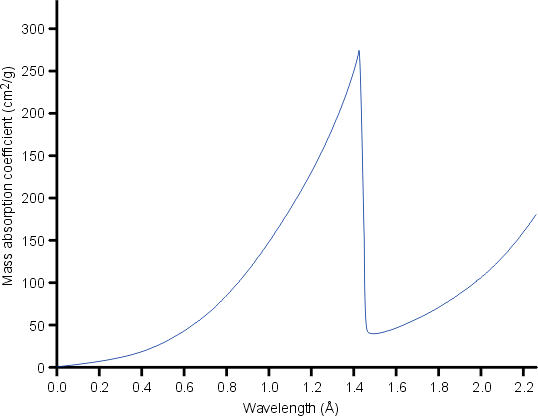
Filters exploit the X-ray absorption edge of the particular element. At wavelengths longer than the absorption edge (i.e. just above the edge), the absorption of the X-rays is considerably less than for wavelengths shorter than the absorption edge (i.e. just below the edge) as shown below for nickel metal:

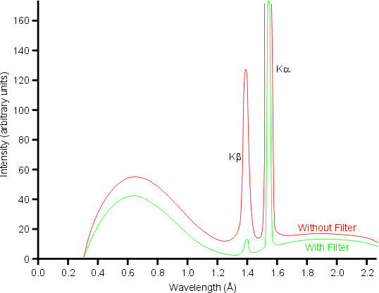
The absorption edge of nickel metal at 1.488 Å lies between the Kα (λ = 1.542 Å) and Kβ (λ = 1.392 Å) X-ray spectral lines of copper. Hence nickel foil of an appropriate thickness can be used to reduce the intensity of the Cu Kβ X-rays as shown below:

Note that the filter also removes much of the high energy background radiation.
The choice of filter material depends upon the choice of anode material in the X-ray tube as shown in the following table:
| Anode | Cu | Co | Fe | Cr | Mo | |||||
|---|---|---|---|---|---|---|---|---|---|---|
| Filter | Ni | Fe | Mn | V | Zr |
From the table it can be seen that the ideal choice of material for an X-ray filter is a metal whose atomic number, Z, is one less than that of the anode target metal for first row transition metals (or two less for second row transition metals).
The optimum thickness, x of the filter can be determined from the mass-absorption law:
| Thickness (cm) | I / Io (%) for Cu Kα | I / Io (%) for Cu Kβ | Reduction Ratio | |||
|---|---|---|---|---|---|---|
| 0.0010 | 64.5 | 7.8 | 8 | |||
| 0.0015 | 51.8 | 2.2 | 24 | |||
| 0.0020 | 41.6 | 0.6 | 68 | |||
| 0.0025 | 33.4 | 0.2 | 197 |
It can be seen from the table that the optimum thickness has to be a compromise between reducing the intensity of the unwanted Cu Kβ and reducing the intensity of the desired Cu Kα. Most commercial systems employing a nickel filter with a copper anode target will choose the thickness of the foil so as to give a reduction ratio in the range 25:1 to 50:1, i.e. foils between 15 and 20 µm thick. From the table, it can be seen that this range of foil thickness will diminish the desired radiation by approximately a factor of 2.
| © Copyright 1997-2006. Birkbeck College, University of London. | Author(s): Jeremy Karl Cockcroft |