Answers to Problem Set 1 - Neil Hyatt.
The links below provide short-cuts to answers for each question, at the end of each answer
a link provides a short-cut to return to the top of this document.
Question 1
Question 2
Question 3
Question 4
Question 5
Question 1
The equation for X-ray absorption is:
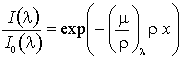
at l=1.54Å, (m/r)l = 230cm2/g
r = 11.3 g/cm3; I(l) = 10 ph/s, Io(l) = 108 ph/s
Substituting these values into the above equation:
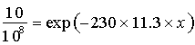
By arthimnetic, this gives the thickness (x) of lead foil required:
x = 0.0062 cm.
Converting to millimeters: required thickness is 0.0620 mm.
If the copper X-ray source is unfiltered and non-monochromated, a continuous spectrum of X-rays will be obtained
(the Bremstraalung) together with high intensity X-rays at discrete wavelengths (characteristic radiation). Although
the lead foil will be sufficient to attenuate X-rays of wavelength 1.54Å it will not be sufficient to attenuate
X-rays of lower wavelength. The Cu-Ka line at 1.54Å arises from 2p-1s transitions in the Cu-atoms of the target,
following ionisation by a fast electron with an energy greater than a critical value. The Kb-line at 1.39Å, arises
from a higher energy 3p-1s transition in ionised Cu-atoms, and is of considerable intensity. The lead foil will not
be effective in attenuating the Kb-X-rays and low wavelength X-rays of the Bremstraalung
(although these are of much lower intensity) because the X-ray absorption coefficient of lead is wavelength dependent,
and smaller at lower wavelengths. Due to the exponentional relationship in the X-ray absorption equation above, a much thicker
piece of lead foil will therefore be required to attenuate the low wavelength X-rays, in the case of an unfiltered non-monochromated copper source.
Question 2
Problems with specimen transparency may arise in samples composed of essentially 'light' (low Z) elements - for example, 'organic' compounds
composed principally of H, C, N, O. In flat plate geometry, the incident X-ray beam penetrates the sample to a greater degree than is
normally the case. This leads to a displacement error in which different parts of the sample (at different depths) are effectively shifted
off the focussing circle in conventional Bragg-Brentano geometry and thus contribute to scattering slightly below the true Bragg angle,
leading to reflection broadening.
In laboratory flat plate Bragg-Brentano geometry, the effects of sample displacement may be reduced by reducing the sample thickness, thereby
alleviating the problem of sample penetration by the incident X-ray beam. This may be achieved by dispersing the sample as a very thin layer
on a single crystal silicon sample holder (with the silicon crystal cut such that the crystal planes do not fulfill the Bragg condition). In this
case the sample depth is only a few crystallite-diameters deep. The diffraction of the incident beam is therefore confined to a very small sample
depth, effectively eliminating sample transparency effects. X-rays fully penetrating the sample are absorbed or diffracted by the silicon sample
holder.
In angle dispersive synchrotron diffraction the X-ray beam is highly collimated and the sample is illuminated by a near parallel beam of X-rays.
This is in contrast to laboratory Bragg-Brentano geometry, where the incident X-ray beam is divergent on the sample at the center of the focussing
circle, with the diffracted beam focussed to a point on the circle circumference - a narrow receiving slit prior to the detector is used to limit
divergence effects. Due to the parallel X-ray beam used in synchrotron powder diffraction, no focussing of the X-ray beam is required and an
analyser crystal is used to limit divergence effects and improve resolution by only passing on to the detector diffracted X-rays with the same
wavelength as those provided by the primary beam monochromator. The benefit of this arrangement in terms of alleviating the effects of sample
transparency, is that the detector samples all diffracted X-rays from the sample which fulfill the Bragg condition at the analyser - irrespective
of their point of origin in the sample. This arrangement effectively eliminates sample displacement effects in angle dispersive synchrotron experiments.
(Reference: J.B. Hastings, W. Thomlinson and D.E. Cox, J. Appl. Cryst., 17, 85, (1984)).
Question 3
The Bragg equation relates d-spacing, wavelength and angle:

We are dealing with the Si(111) relectrion with d-spacing: d = 3.136Å.
For a wavelngth l = 0.70Å, substitution into the Bragg equation gives the initial angle (qi) of the monochomator:
Thus: 0.70 = 2 x 3.136 x sinqi
Giving: sinqi = 0.1056
Hence: qi = 6.0586o
For a wavelngth l = 0.65Å, substitution into the Bragg equation gives the final angle (qf) of the monochomator:
Thus: 0.65 = 2 x 3.136 x sinqf
Giving: sinqf = 0.1036
Hence: qf = 5.9485o
The monochromator must be moved through an angle corresponding to the difference between the initial and final angles:
Hence monochromator must be moved through 5.9485 - 6.08588 = -0.1103o.
The monochoromator must therfore be moved through 0.1103o, toward the horizontal.
Question 4
Substitution of the relationship E = 12.398 / l into the Bragg equation (see Question 3) yields:
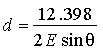
Substituting E = 20 KeV (with q = 3.5o / 2 = 1.75o), we obtain the maximum d-spacing:
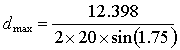
Thus: dmax = 10.1495Å
Substituting E = 100 KeV (with q = 3.5o / 2 = 1.75o), we obtain the minimum d-spacing:
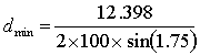
Thus: dmin = 2.0302Å
Therefore the range of d-spacings between 2.0302Å and 10.1495Å, may be measured.
Question 5
i. -x, y, -z
The corresponding symmetry element is a two fold rotation axis along the y-axis (i.e. along
the line (0, y, 0)). This would convert x to -x and z to -z but leave y unchanged.
ii. 1/2+x, 1/2+y, 1/2+z
I am stumped with this one... I can see that this symmetry operator would relate a lattice point at the origin of a
body centred unit cell to the lattice point at the body center - but I can't see how this arises from a single symmetry
operation of a rotation / reflection / inversion / screw / glide type.
iii. -x, -y, -z
The corresponding symmetry element is an inversion center at the origin. This would
convert the values of x, y and z to -x, -y and -z.
iv. -x, -y, 1/2+z
The corresponding symmetry element is a 21 screw axis along the z-axis (i.e. along
the line (0, 0, z)). A two fold rotation about the z-axis will convert x to -x and y to -y,
but leave z unchanged, a translation of 1/2 c along z will then convert z to 1/2+z, but
leave the values of x and y unchanged. Overall this converts x to -x, y to -y and z to
1/2+z.
v. x, y, -z
The corresponding symmetry element is a mirror plane in the x,y-plane at z = 0, i.e.
passing through the origin and perpendicular to the z-axis. Reflection in the mirror
plane leaves x and y unchanged but converts z to -z.
vi. 1/2+x, -y, z
The corresponding symmetry element is an a-glide plane in the x,z-plane at y = 0, i.e.
passing through the origin and perpendicular to the y-axis. Translation of 1/2 a along x
will convert x to 1/2+x, reflection in the mirror plane will leave x and z unchanged, by
convert y to -y. Overall this converts x to 1/2+x, y to -y and leaves z unchanged.
vii. 1/2+x, -y, -z
The corresponding symmetry element is 21 screw axis along the x-axis, (i.e. along
the line (x, 0, 0). A two fold rotation about the x-axis will convert y to -y and z to -z,
but leave x unchanged, a translation of 1/2 a along x will then convert x to 1/2+x, but
leave the values of y and z unchanged. Overall this converts x to 1/2+x, y to -y and z
to -z.
viii. 1/2+x, 1/2+y, z
Hmmm... I am stumped with this one too! I can see that this symmetry operator would relate a lattice point
at the origin of a C-centred unit cell to one of the lattice points at a face center - but I don't see how this arises from a single symmetry
operation of a rotation / reflection / inversion / screw / glide type. I first thought that the translational components to x and y suggested
the symmetry element might be a two fold rotation axis displaced from the origin, but in this case I can't work
out what the displaced x,y-coordinates are. I then thought that the translational components might be symptomatic of an n-glide plane,
but in this case (an n-glide plane in the x,y plane) I would end up with z being transformed to -z, which is
obviously incorrect! My final thought was that a mirror plane parallel to the line (1/2, 1/2, 0) and
normal to the x,y plane might do the trick - because this would transform x and y by the same amount, but leave z unchanged
since the mirror plane is parallel to the z-axis, but I can't see how to work out how this mirror plane is displaced from
the origin in this case.
ix. 1/2-x, 1/2-y, z
The corresponding symmetry element is a two fold rotation axis at (1/4, 1/4, z), i.e. parallel to the
z-axis and normal to the x,y-plane. Using the derivation given in the Rotational Symmetry
section, one can show that for a general displacement of a two fold rotation axis from
(0, 0, z) (i.e. along the z-axis) to (Tx, Ty, z), the x and y positions transform as:
x converts to 2Tx-x
y converts to 2Ty-y
Thus, to determine the values of Tx and Ty, the following equations must be solved:
2Tx - x = 1/2 - x giving Tx = 1/4
2Ty - y = 1/2 - y giving Ty = 1/4
Thus the two fold rotation axis displaced to (1/4, 1/4, z), parallel to the z-axis and normal to the x,y plane. This converts x
to 1/2-x, y to 1/2-y but leaves z unchanged.
x. x, 1/2-y, z
The corresponding symmetry element is a mirror plane, normal to the y-axis (in the x,z-plane), displaced to y = 1/4.
Reflection of a point (x, y, z) in the mirror plane will leave x and z unchanged, as shown below:
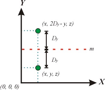
The difference in Y between the position of the point and the mirror plane after the symmetry operation is y-Dy.
Thus the y-coordinate after the symmetry opertation is:
y - 2(y - Dy) = 2Dy - y
In order to determine the displacement of the mirror plane along the y-axis the following equation must be solved:
2Dy - y = 1/2 - y giving Dy = 1/4
Thus a mirror plane normal to the y-axis (in the x,z plane) displaced to y = 1/4, will leave x and z unchanged but convert y to 1/2-y.
Author: Neil Hyatt, University of Birmingham, January 2000.